Loudspeaker System Design
Spacemap Go Help
by Bob McCarthy
There are an unlimited number of ways to design a loudspeaker system for immersive experiences; it depends on what you want the audience experience to be; it is an artistic decision. A minimum of two loudspeakers and two processor outputs are required for panning using Spacemap Go. Beyond that, a Spacemap Go loudspeaker system has no restrictions.
A typical loudspeaker system used to amplify or reproduce audio sources is designed for minimum overlap of loudspeaker coverage, where each audience location receives correlated signals from the minimum number of sources. Spacemap Go loudspeaker system designs are different: each audience location is covered by all of the loudspeakers. Each audience member can receive uncorrelated signals from all the loudspeakers, depending on the artistic desires.
The system design information below is a guide to selecting loudspeaker models, locations, and aiming for an immersive Spacemap System. The goal of this example immersive system is to provide continuous panning from one sound source to another, observable by the maximum number of audience members, allowing the audience to localize a source anywhere within half of a sphere. We will refer to this set of criteria as a “granular system.” Other design goals may use different system design methods, which are completely valid. Please contact Meyer Sound or solicit ideas from the Spacemap Go Forum (link above) if you have questions or comments.
Video References
Bob’s Origami Method A tangible method to determine locations and spacing for loudspeakers.
System Design Roundtable #1, 2021-01-13 Fundamentals of design and methodology, with Spacemap examples.
System Design Roundtable #2, 2021-01-20 Design examples for various room shapes, with Spacemap examples.
System Design Roundtable #3, 2021-01-27 Design examples with balconies and fills, with Spacemap examples.
Loudspeaker Homogeneity (Sameness)
The loudspeakers used in Spacemap Systems are influential in the audience experience. Type, directivity, and placement affect the overall performance and audience perception.
If the same model of loudspeaker is used at every location and they are working properly, sameness or homogeneity is achieved within the needed parameters. Small variations are not a significant factor. Large ones, like a damaged driver or different phase responses do matter. When a sound is panned from a properly working loudspeaker to one with different acoustic output, the illusion of the sound moving will be disturbed.
Loudspeakers used in Spacemap Systems should be adjusted so that their frequency and phase responses match. When using different models of Meyer Sound loudspeakers from different product families, use Product Integration (Compass software) to match the phase responses from different product families and EQ filters (usually U-Shaping in Compass software) to match the frequency responses.
Room Acoustics
To preserve localization, rooms with low reverberation times and minimal echoes are desirable. Acoustically reverberant and reflective rooms will cause sounds to localize to additional points in the room or become less distinct. If that is not the desired aesthetic, change the acoustic properties of a room, which usually involves adding materials to either enhance or dampen reflections. Selection of loudspeaker models based on directivity and careful aiming of the loudspeakers can change the amount of sound that reaches acoustically reflective surfaces.
Spacemap Go Interactive Application
Spacemap Go at its core is a graphic interface, that has a core function of controlling the summing matrix cross-point levels of GALAXY processors. The iPad interface uses a virtual representation of loudspeaker locations. The locations can mirror the real loudspeaker locations or can be arranged abstractly, in any way desired. If a Speaker Node is at the “rear” of a room, the sound will not move to rear of the room if no loudspeaker is there – no matter what the app displays. Physical reality requires that sound sources exist at milestone locations, allowing Spacemap Go to “pan” a given input between them.
Terminology Used
Lateral System: Loudspeakers placed around the room perimeter, perceived as having a relatively low vertical orientation to the listener, less than 45° above them, e.g., side and rear surrounds.
Overhead System: Loudspeakers placed above the listeners, perceived as having a relatively high vertical orientation to the listener, more than 45° above them.
360° “Fully Granular”: Each loudspeaker is a unique Spacemap node, capable of being perceived as the exclusive image source of a given signal channel.
Coverage Pattern: The range of frequencies in which a loudspeaker model is directional. These are higher frequencies, almost always reproduced by a compression driver and a horn or a dome tweeter, usually above 2 kHz, depending on the model.
In Coverage or Covers: These phrases refer to SPL in a loudspeaker’s coverage pattern. An area is defined as “in coverage,” if the area has less than 6 dB of variation from the loudest point to the quietest point.
Design Criteria
Loudspeaker Coverage
MAPP 3D is used to model the space, loudspeaker locations, and to predict coverage.
The design intention for a “Granular” Spacemap System is:
- Each loudspeaker covers the maximum percentage of listening area.
- For all locations, wide horizontal coverage is strongly advised, 80° minimum, 110° preferred.
- Lateral loudspeakers are intended to reach to the opposite side of the listening area, reduced vertical coverage is preferred, 50° or less.
- Overhead systems benefit from both wide vertical and wide horizontal coverage patterns, 80° minimum, 110° preferred.
Loudspeaker Models
This design method utilizes wide (horizontal) coverage loudspeakers. The family of 110° wide loudspeakers is preferred (current products): LYON-W, LEOPARD, ULTRA‑X40, ULTRA‑X20/23, UP‑4slim, UP‑4XP, HMS‑12, Ashby‑5C/8C, MM‑4XP, MM‑4XPD. The family of 80° to 90° wide loudspeakers may require slightly higher density (current products): LYON‑M, UPQ‑D1/D3, UPJ‑1P, HMS‑5/10/15/15AC.
Design Goals
Before designing a Spacemap Go system, it is important to understand what the artistic and aesthetic goals of system are and what content is intended to be reproduced. If a system will be used to continuously pan a sound horizontally around a space, a Lateral, 360° Granular design is needed (example on the left, below). To smoothly pan above the audience’s heads, an Overhead, 360° Granular design is needed (center, below). To pan a sound from one corner to overhead to the opposite corner, an 360° Fully Granular design is needed (right, below).
For the examples below, the design goals are:
- Multi-channel main system
- Fully granular lateral system
- Fully granular overhead system
- Low frequency system
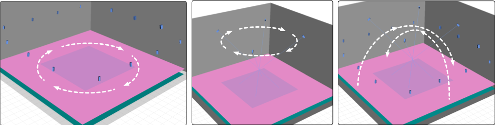
System Design Goals – Lateral Panning (left), Overhead Panning (center), Lateral to Overhead to Lateral Panning (right)
Design Steps
- Define the Space: Loudspeaker Perimeter, Coverage Area, “Go Distance” and “Go Zone.”
- Main System: horizontal spacing, height, horizontal and vertical aim.
- Lateral System: scale for power, height, horizontal spacing, height, horizontal and vertical aim.
- Overhead System: scale for power, locations, height, horizontal spacing, horizontal and vertical aim.
- Low-Frequency System: scale for power, locations.
- Assign signal processing channels.
1. Define the Space
There are many room shapes. To describe the design steps, we will use a room that is square with a high ceiling (22 m x 22 m, 12 m high).
Perimeter: The distance between the wall and the mounting locations of the main and lateral loudspeaker (1 m).
Coverage Area: The area of the room within the Loudspeaker Perimeter (20 m x 20 m).
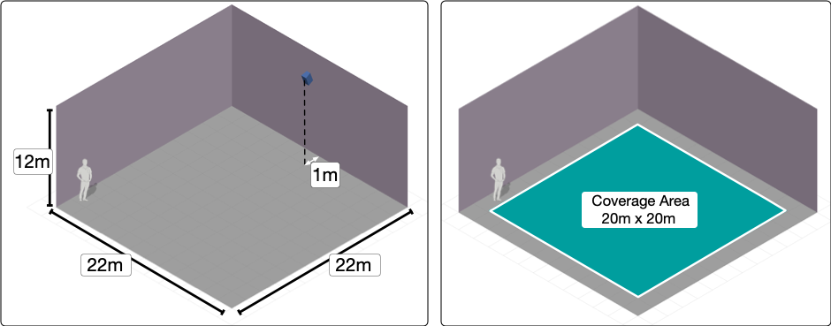
Example Room – Dimensions and Loudspeaker Perimeter (left), Coverage Area (right)
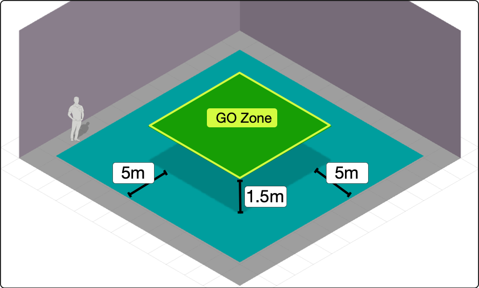
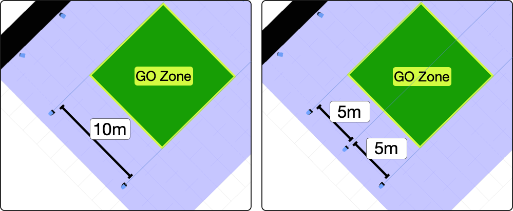
Go Distance: 1/4 the distance of the narrow side of the Coverage Area (20 m x 0.25 = 5 m).
Go Zone: Subtract 1x “Go Distance” (5 m) from all sides and elevate to ear height of the listeners (1.5 m). The narrow side of the Go Zone is 2x the Go Distance (10 m). In this square room, the Go Zone is 2x the Go Distance square (10m x 10 m).
NOTE: The Go Zone and Go Distance provide a scalable reference for identifying loudspeaker locations and do not define the immersive experience area. The immersive experience area can be as large as the loudspeaker parameter, if the loudspeaker positions and loudspeaker directivity are optimal.
Example Room – Dimensions and Loudspeaker Perimeter (left), Coverage Area (right)
2. Main System
To meet the design goals for this example, the Main loudspeakers should have a narrower vertical and wider horizontal coverage. Beyond directivity, bandwidth and SPL needs to reproduce the desired signals versus the loudspeaker capabilities should be considered.
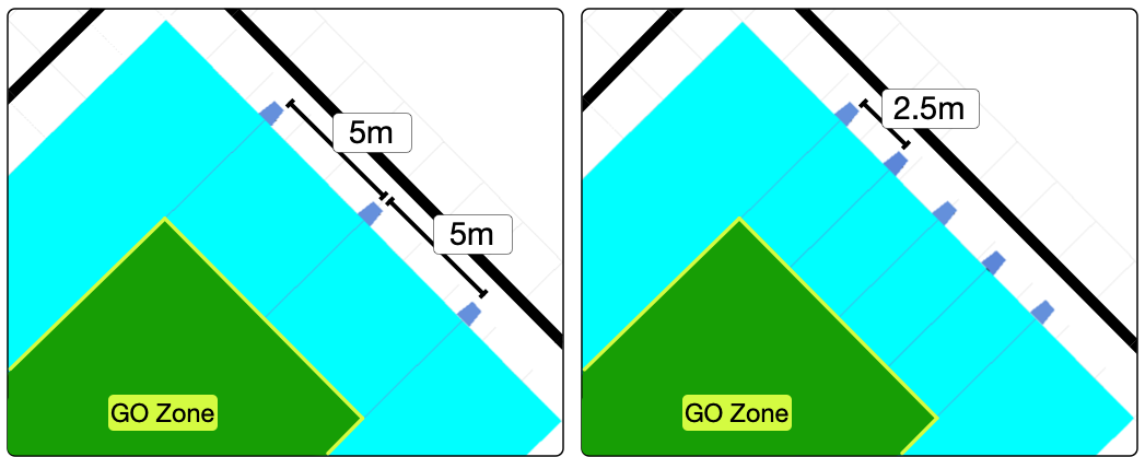
Main System Horizontal Spacing:
Spread the loudspeakers to fill a length of 2x the Go Distance (10 m).
Example 1: Three Mains Scenario – Spread the mains horizontally to fill a length of 2x Go Distance (10 m), horizontal spacing of 5 m. The outer mains are in line with the edges of the Go Zone.
Example 2: Five Mains Scenario – Spread the mains horizontally to fill a length of 2x Go Distance (10 m), horizontal spacing of 2.5 m
Example 3: If using higher SPL models as primary Left/Right anchors, with lower SPL models used in secondary positions: spread the loudspeakers horizontally to fill a length of 2x Go Distance (10 m). Use the outer positions or the second and forth positions for the Left/Right anchors.
Main System – Three and Five Loudspeakers
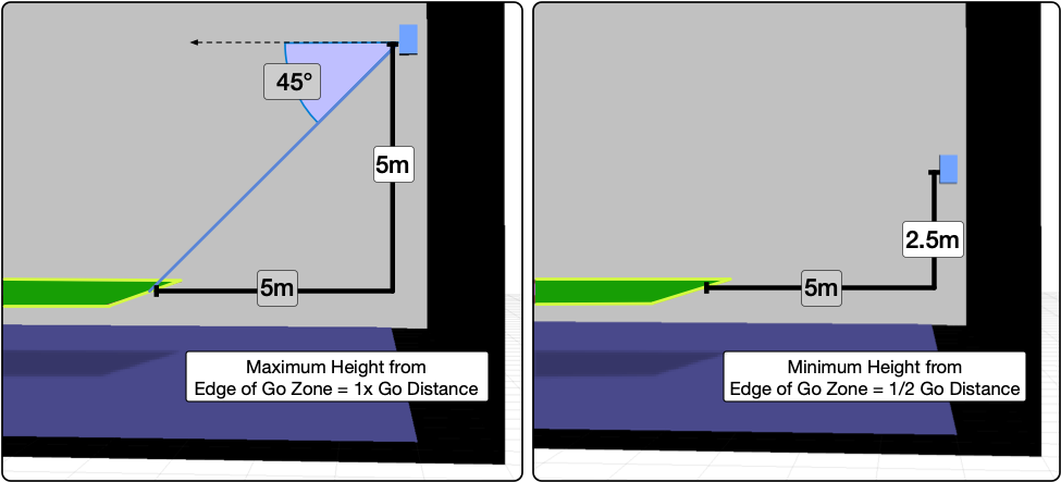
Main System Height:
Maximum: One Go Distance above the Go Zone (5 m), less than 45° downtilt to closest edge of Go Zone.
Minimum: 1/2 Go Distance above the Go Zone (2.5 m).
Usually, maximum height yields the most uniform coverage.
Main System – Maximum and Minimum Height
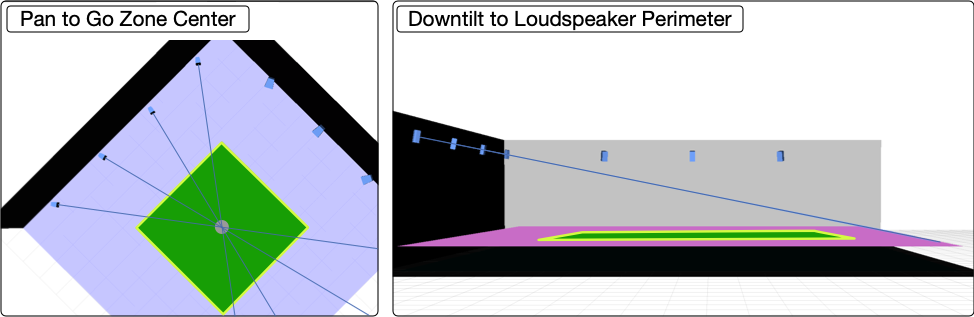
Mains System Aiming:
Pan (horizontal) to middle of Go Zone.
Tilt (vertical) to opposite Loudspeaker Perimeter.
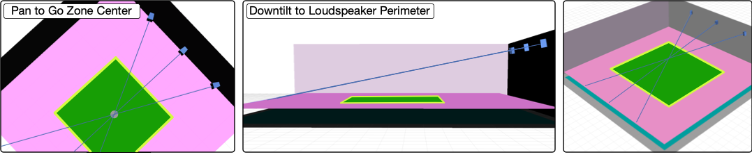
Main System Aim – Pan Through Center of Go Zone, Downtilt to Loudspeaker Perimeter
Mains Coverage Verification
One way to simplify verification of loudspeaker coverage, is to adjust the SPL preferences in MAPP 3D:
- To make coverage easier to identify, change the preferences in FILE > PROJECT SETTINGS, SPL Tab to be ATTENUATION mode, Range = 12 dB, 6 dB/color.
- Set the Prediction Parameters to 1 Octave, 4kHz. This frequency range is representative of the high-frequency coverage of most loudspeaker models.
- The prediction data in red represents 0 dB to -6 dB of attenuation and we will call that “in coverage.” The Go Zone should be completely red or very close to it.
NOTE: All MAPP 3D predictions below use these settings unless otherwise stated.
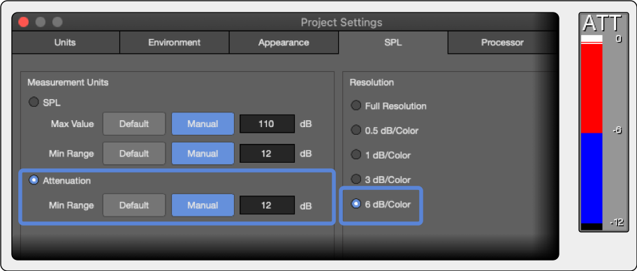
MAPP 3D Project Settings, SPL Tab, Attenuation Settings
Ideally, each loudspeaker provides the same coverage for each audience location. Because that is not realistic, we work towards that goal. Spill outside the Go Zone is great! But, if the walls above listener height are in coverage, consider a loudspeaker model with a narrower pattern. If a loudspeaker model provides less than 75% coverage in the Go Zone (relative, 0 dB to -6 dB), use a loudspeaker with different directivity or change the height and aim.
Example 1: The ULTRA‑X40 (110° vertical x 50° horizontal ) at the maximum height (6.5 m, 1.5 m listener height + 5 m Go Distance), provides uniform coverage from each main position for this space (below).
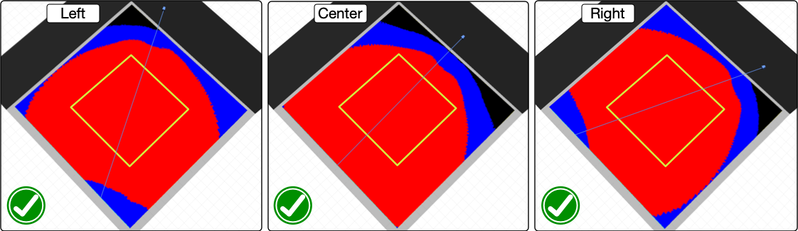
Main System Coverage Verification – Good Go Zone Coverage Achieved (ULTRA‑X40, 110° Horizontal)
Example 2: With the ULTRA‑X40’s in the same location and the horns rotated (50° horizontal x 110° vertical), the coverage is insufficient, below.
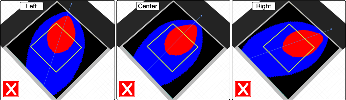
Main System – Insufficient Coverage, ULTRA‑X40 Horns Rotated to 50° Horizontal
Example 3: As the height of the center loudspeaker is changed, the coverage is affected. The downtilt is adjusted for each height, always at the opposite edge of the coverage area. The coverage area decreases as loudspeaker height is lowered from 1x Go Distance (5 m) to 1/2x Go Distance (2.5 m).
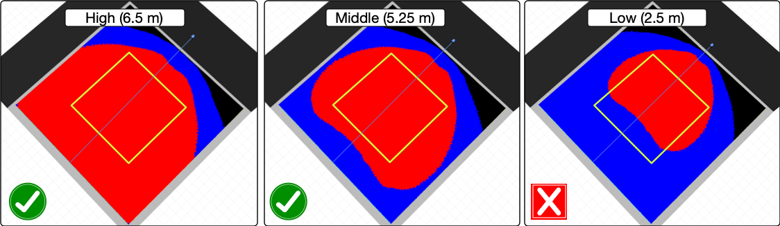
Main System – Maximum, Middle, and Minimum Height Effects Coverage
3. Lateral System
Like the mains, select models with wide horizontal coverage and more narrow vertical coverage.
Lateral System – Power Scaling: The maximum SPL output of a loudspeaker in the Go Zone is dependent on your relative power needs. It is a decision based on creative needs – what sound needs to be reproduced at what maximum level? If the surrounds must reproduce signals at the same level as the mains – then they require an equal power scale. If the surrounds need to only supplement the mains, they can be 6 to 12 dB less in power scale or more, depending on the desired SPL.
Example 1: Leopard Mains – equal power = ULTRA‑X40 surrounds, reduced power = ULTRA‑X20
Example 2: ULTRA‑X40 mains – equal power = ULTRA‑X20 surrounds, reduced power = UPJ‑1P
Lateral System – Height: (same as main system)
Maximum: One Go Distance (5 m) above Go Zone (1.5 m), less than 45° downtilt to closest edge of Go Zone.
Minimum: 1/2 Go Distance (2.5 m) above Go Zone (1.5m).
Lateral System, Sides – Horizontal Spacing:
Locate first and last Side Surround 1/2 Go Distance beyond the Go Zone (5 m / 2 = 2.5 m).
Nominal spacing for the Side Surrounds is the Go-Distance (5 m). Fill between first and last Side Surround at evenly spaced intervals, not exceeding 1x Go Distance.
Lateral System, Side Locations – First and Last 1/2 Go Distance Outside Go Zone (left), Fill Between (right)
Lateral System, Rear – Horizontal Spacing:
Locate the first and last Rear Surrounds at the edges of the Go Zone (2x Go Distance apart).
Nominal spacing for the Rear Surrounds is the Go Distance (5 m). Fill between first and last Rear Surround at evenly spaced intervals, not exceeding 1x Go Distance.
Lateral System, Rear Locations – First and Last Loudspeaker Aligned with Go Zone Extents, Fill Between
Lateral System – Aiming: (same as Main System)
Pan (horizontal) to middle of Go Zone
Tilt (vertical) to opposite Loudspeaker Perimeter.
NOTE: The center lines of the Meyer Sound HMS models from the CINE-STUDIO Series differ slightly from the center of the acoustic output: HMS‑15 and HMS‑10 aim 2°‑low, HMS‑5 aim 2°‑higher.
Lateral System, Sides – Pan to Center of Go Zone, Downtilt to Opposite Loudspeaker Perimeter
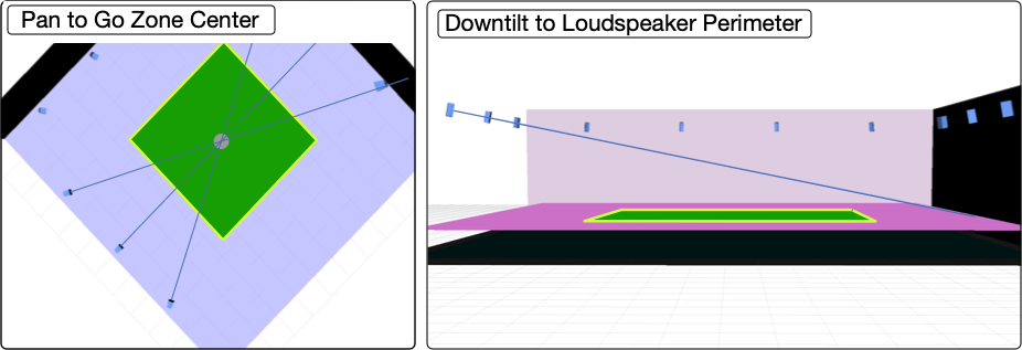
Lateral System, Rears – Pan to Center of Go Zone, Downtilt to Opposite Loudspeaker Perimeter
Lateral Coverage Verification
Use the same verification method for the side and rear laterals as was used for the mains: target the Go Zone and cover as much of the entire space as possible without covering the walls above listening height. If coverage is not sufficient, adjust the height and downtilt and/or try another loudspeaker model.
Example 1: The ULTRA‑X20 (110° vertical x 50° horizontal ) at the maximum height (6.5 m, 1.5 m listener height + 5 m Go Distance), provides uniform coverage of the Go Zone from each Lateral Side position for this space.
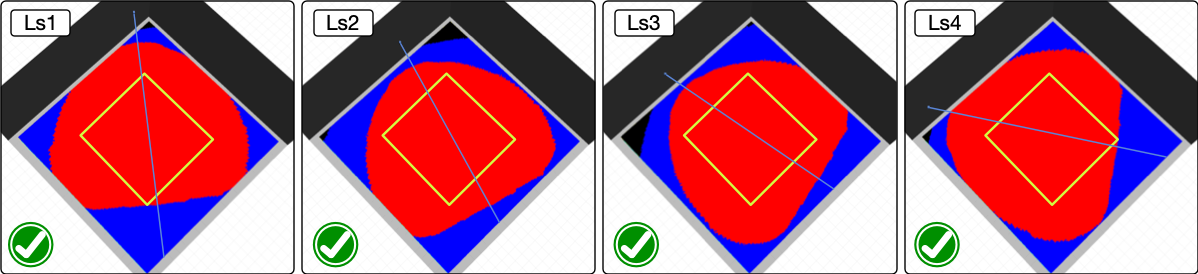
Lateral System, Sides – Coverage Verification, Good Go Zone Coverage Achieved (ULTRA‑X20, 110° Horizontal)
4. Overhead System
These positions will benefit from a model selection that has both a wide horizontal and vertical coverage pattern.
Overhead System – Power Scaling: The maximum SPL output of a loudspeaker in the Go Zone is dependent on your relative power needs. If the overheads must reproduce signal at the same level as the mains – then they must have equal power scale. If the overheads need only supplement the mains, then they can be 6 to 12 dB down in power scale.
Example 1: Leopard Mains – equal power = ULTRA‑X40 surrounds, reduced power = ULTRA‑X20
Example 2: ULTRA‑X40 mains – equal power = ULTRA‑X20 surrounds, reduced power = UPJ‑1P
Overhead System – Height:
Maximum: 2x Go Distance (10 m) above the Go Zone (1.5 m)
Minimum: 1x Go Distance (5 m) above the Go Zone (1.5 m)
Maximum height usually provides more coverage area.
Overhead System – Horizontal Spacing:
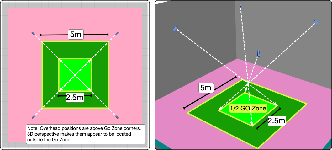
Locate loudspeakers above the corners of the Go Zone. On the long side of a rectangular room, if the distance between the Go Zone corners is between 1x and 2x Go Distances, consider adding a loudspeaker between the corners. If the distance is 2x Go Distances or more, add evenly spaced loudspeaker positions at 1x Go Distance spacing.
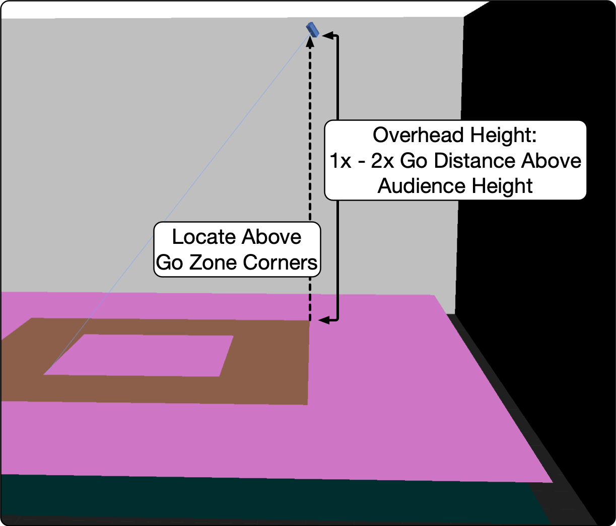
Overhead System – Locate above Go Zone Corners, Height Between 1x and 2x Go Distance
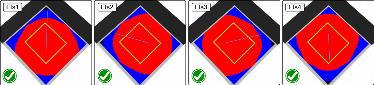
Overhead System – Aiming:
Pan (horizontal) through middle of the Go Zone
Tilt (vertical) to 1/2 Go Distance past the center of the Go Zone.
Overhead System Aiming – Pan Through the Go Zone Center, Tilt to 1/2 Go Zone Corners
Overhead Coverage Verification
Again, target the Go Zone and cover as much of the entire space as possible without covering the walls above listening height. Adjust the height or select another loudspeaker model if coverage is not sufficient.
Example 1: The ULTRA‑X23 (110° vertical x 110° horizontal) at the maximum height of 2x Go Distance (11.5 m, 1.5 m listener height + 2x Go Distance, 10 m), provides uniform coverage of the Go Zone from each Overhead position for this space.
Overhead System – Coverage Verification, Good Go Zone Coverage Achieved (ULTRA‑X23, 110° x 110°)
5. Low-Frequency System
Low-Frequency Power Scaling: The maximum SPL output of a subwoofer is dependent on your relative power needs in lower frequencies when compared to the SPL capabilities of the mid-high loudspeakers. Usually, subwoofers used with the main mid-high system can reproduce at least the same in-band SPL as the mid-high models, but commonly more(e.g., 6 to 12 dB. Subwoofers used with the lateral and overhead system are usually scaled with the mid-high models used, may be extremely over-specified, or not used at all, depending on the expected content and maximum SPL needs.
Low-Frequency Locations: Because lower frequencies are more difficult to localize, fewer locations are required than the mid-high loudspeakers for effective low-frequency panning.
For the subwoofers paired with the main/front system, the scaling criteria and locations are the same used with a typical system. Single elements or arrays are used, flown or ground stacked, to achieve the coverage uniformity and SPL as desired. For the lateral and overhead systems, it is important to understand what the intended reproduction signals are, how loud they need to be reproduced, and the amount of localization desired. It may be that a single, lower-powered subwoofer on each side wall is sufficient for reproducing lower-level, atmospheric content, while reproducing the sound of giant creature footfalls might require many positions, and as much power as the main system subwoofers. Overhead subwoofers can be used to convincingly reproduce a sound that has low-frequency content above the audience.
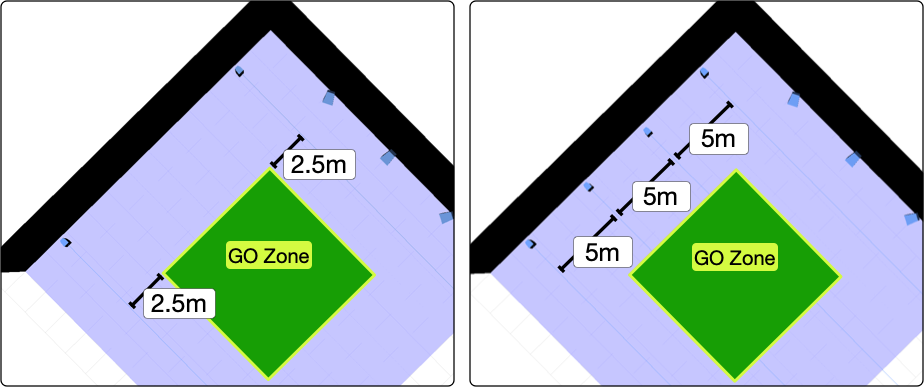
Low-Frequency Examples: On the left, four subwoofers augment the output of the Main or Frontal System. Two subwoofers are located in the rear corners to augment the Side and Rear Systems. On the right, the Main Subwoofer Array is arranged in a spaced line and utilizes delay offset to increase the width of coverage, the outer pair is delayed 2 ms and the middle pair 1 ms, relative to the center subwoofer. The Overhead Subwoofer Array is directional. The rear element is polarity reversed, delayed 2.9 ms, and is 1 m above the bottom element. Spacemaps can be created to pan between these arrays or individual elements within an array.
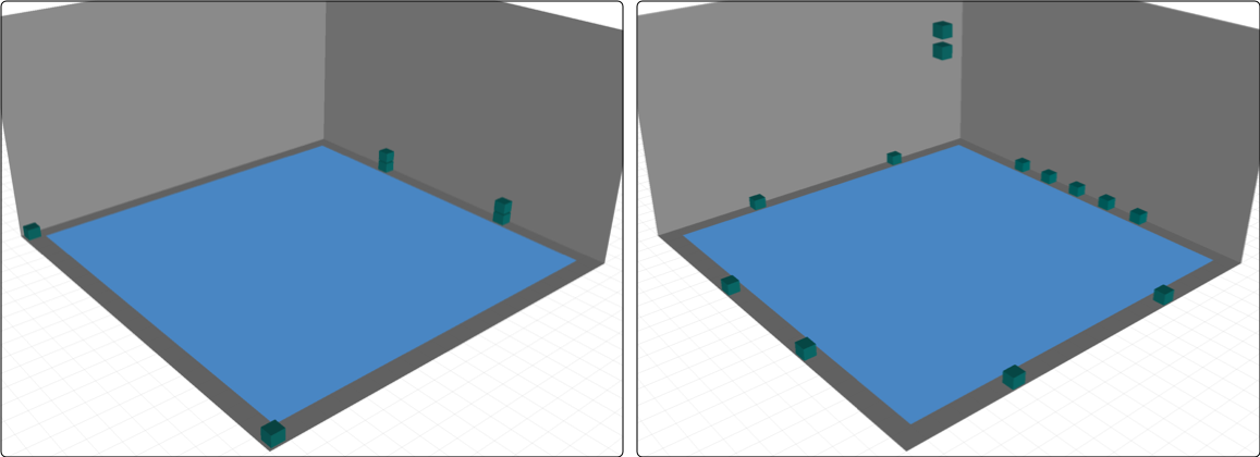
Subwoofer System – Less Localization (left), More Localization (right)
6. Signal Processing Channel Assignments
For maximum panning control, each GALAXY processor output is connected to an individual loudspeaker or an array of loudspeakers. When one processor output is connected to multiple loudspeakers, panning between the loudspeakers is not possible. If panning within an array is not needed, a single Spacemap Go processor output can be used as an input, routed to several outputs connected to an array, and/or used for inner-array optimization.
Variations of Room Geometry
This design method is also used for rooms that are not square. Find out how in this video: System Design Roundtable that includes design examples for non-square rooms, design strategies used with balconies and fills, and concludes with several Spacemap examples.
00:00-10:00 Review of the Above Design Methodology
10:00-41:30 Design Methodology in Non-Square Rooms
41:30-end Example Spacemaps